A TFT (Thin-Film Transistor) display is a specific variant of Active Matrix Liquid Crystal Display (AMLCD) technology. Unlike passive matrix screens that rely on a simple grid to control pixels, a TFT screen incorporates a dedicated transistor and capacitor for every single pixel on the panel. This architecture allows for precise, rapid, and independent control of each pixel, resulting in superior image stability, faster response times, and significantly higher contrast compared to older display technologies. In essence, when people refer to a “TFT screen” today, they are almost always talking about the high-quality LCD panels found in everything from smartphones and laptops to industrial control panels and automotive dashboards.
Understanding the Technology: Beyond the Acronym
Having spent over a decade working with embedded systems and display integration, I’ve seen the evolution of screens from grainy, ghosting passive matrices to the crisp, vibrant TFTs we take for granted now. The core innovation here isn’t just the liquid crystal itself, but the backplane technology—the layer of transistors sitting behind the glass.
In a standard LCD, liquid crystals twist and untwist to block or allow light from a backlight to pass through color filters. The challenge has always been: how do you tell a specific pixel to change state without affecting its neighbors?
Passive matrices (like old STN screens) addressed this by scanning rows and columns, which led to crosstalk and slow refresh rates. TFT solves this by placing a microscopic switch (the thin-film transistor) at every pixel intersection. When the gate line activates the transistor, charge flows from the data line into the pixel’s storage capacitor. This capacitor holds the voltage steady until the next refresh cycle, ensuring the pixel remains exactly as bright or dark as intended, regardless of what neighboring pixels are doing. This “active” control is why TFTs don’t suffer from the “ghosting” effects of the past.
Most modern TFTs use Amorphous Silicon (a-Si) for the transistors due to its cost-effectiveness and uniformity over large areas. However, for high-end applications requiring faster switching or transparency, you might encounter Low-Temperature Polysilicon (LTPS) or even Oxide (IGZO) TFTs, which offer higher electron mobility.
Key Characteristics of TFT Displays
When evaluating a TFT panel for a project, I usually look at a specific set of parameters that define its performance envelope. These aren’t just marketing buzzwords; they are hard engineering constraints.
| Fonctionnalité | Description & Technical Context |
|---|---|
| Active Matrix Architecture | Each pixel has a dedicated transistor/capacitor pair, enabling precise voltage retention and eliminating crosstalk. |
| High Resolution & Density | Capable of supporting high PPI (Pixels Per Inch), making text sharp and images detailed, essential for modern UIs. |
| Fast Response Time | Typically ranges from 5ms to 25ms (gray-to-gray), sufficient for video playback and dynamic UI transitions without blur. |
| Wide Color Gamut | Depending on the backlight (LED vs. CCFL) and filter quality, TFTs can cover sRGB, Adobe RGB, or DCI-P3 standards. |
| Viewing Angles | Varies by alignment technology (TN vs. IPS). Standard TN panels have narrow angles, while IPS-based TFTs offer near 178° visibility. |
| Brightness Control | Supports PWM (Pulse Width Modulation) or DC dimming for backlight adjustment, crucial for power management and outdoor readability. |
Weighing the Pros and Cons
No technology is perfect. In my experience selecting displays for battery-powered IoT devices versus mains-powered industrial HMIs, the trade-offs become very apparent. While TFT is the industry standard for a reason, it’s not always the right choice for every application (e.g., e-paper might be better for static signage).
| Advantages | Disadvantages |
|---|---|
| Superior Image Quality: Excellent color reproduction and sharpness compared to passive matrices or OLEDs in some brightness scenarios. | Consommation électrique: Requires a constant backlight, making it less energy-efficient than reflective displays (like E-ink) or OLEDs showing dark images. |
| Cost-Effectiveness: Mature manufacturing processes make a-Si TFTs incredibly cheap per inch, especially in mass production. | Limited Contrast Ratio: Because the backlight is always on, true blacks are difficult to achieve (light leakage), unlike OLED which turns pixels off completely. |
| Long Lifespan: No organic materials to degrade (burn-in) like OLEDs; backlights can last 50,000+ hours. | Viewing Angle Limitations (TN type): Cheap TN panels suffer from color shifting and inversion when viewed from the side (though IPS solves this at a higher cost). |
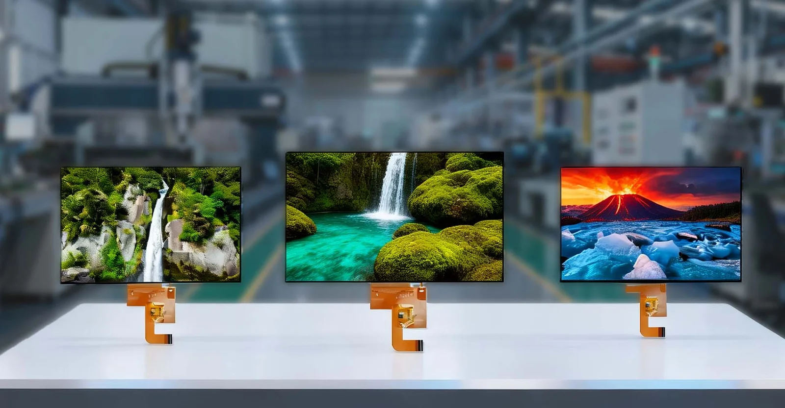
| Scalability: Can be manufactured in very large sizes (TVs) or very small sizes (wearables) with consistent yield. | Complexity: Requires complex driver ICs and timing controllers, making the interface design more demanding than simple segment LCDs. |
| Sunlight Readability: High-brightness variants (1000+ nits) are available for outdoor use, outperforming many OLEDs in direct sun. | Thickness: The backlight unit adds bulk, preventing the ultra-thin form factors achievable with OLED. |
Real-World Applications
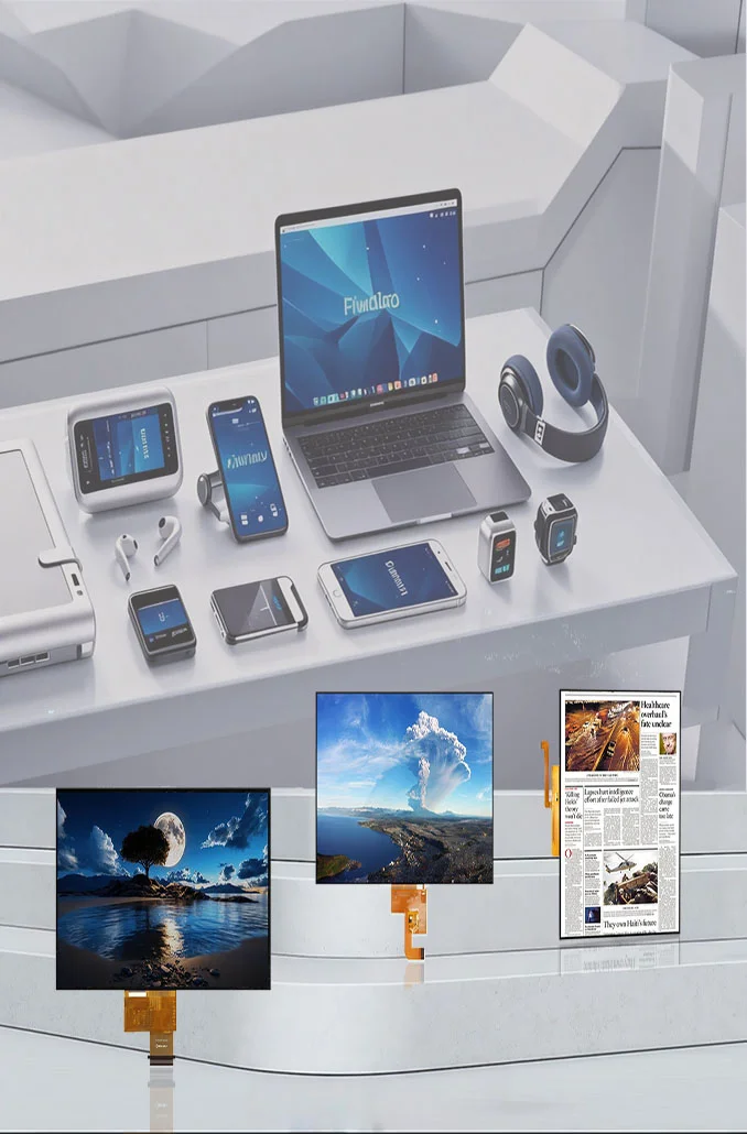
The ubiquity of TFT technology means you interact with it dozens of times a day. Based on current market trends and my own project history, here is where TFTs dominate:
- Électronique grand public: Smartphones, tablets, laptops, and smartwatches. Here, IPS-TFT is the norm due to color accuracy and viewing angles.
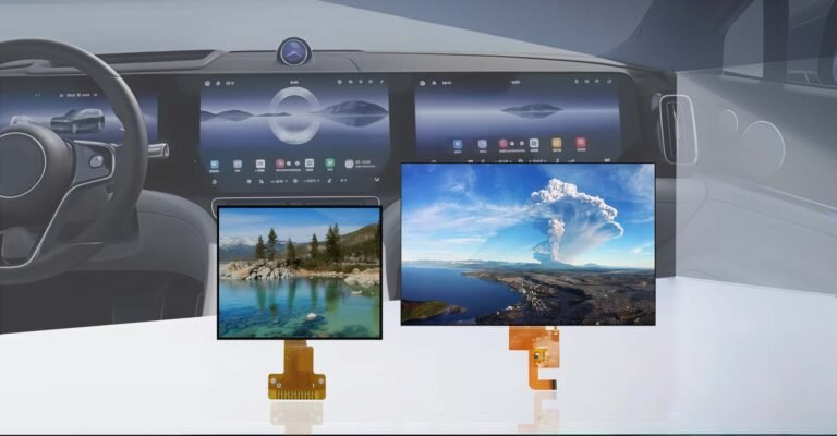
- Automobile Interfaces: Modern cars rely on TFTs for digital instrument clusters, infotainment systems, and rear-seat entertainment. These require specialized grades capable of withstanding extreme temperatures (-40°C to +85°C) and high vibration.
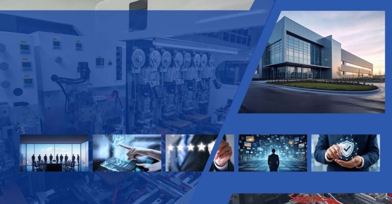
- Industriel HMI (Human Machine Interface): Factory control panels, medical devices, and POS terminals. Reliability and long-term availability (often 5-10 year lifecycle guarantees) are key here.
- Home Appliances: Smart refrigerators, washing machines, and thermostats are increasingly adopting TFTs to replace physical buttons with intuitive GUIs.
- Aviation & Marine: Cockpit displays and navigation systems where readability under varying light conditions is critical for safety.
How to Select the Right TFT for Your Project
Selecting a display isn’t just about picking the biggest screen with the highest resolution. Over the years, I’ve learned that skipping the “boring” specs leads to field failures. Here is my practical checklist for selection:
- Define the Environment First: Will this be used indoors or outdoors? If outdoors, you need high brightness (>800 nits) and possibly an optical bonding process to reduce reflection. If it’s for a car or factory, ensure the panel is rated for the operating temperature range.
- Interface Compatibility: Check your processor’s capabilities. Do you have an RGB interface, MIPI DSI, SPI, or LVDS? High-resolution screens usually require MIPI DSI, while smaller ones might work with SPI. Don’t pick a 4K screen if your MCU only supports 8-bit parallel.
- Touch Integration: Do you need capacitive touch (PCAP) or resistive? PCAP is standard for consumer feel but requires a controller and calibration. Resistive is better for gloved operation or harsh industrial environments.
- Viewing Angle Requirements: If the user will view the screen from the side (e.g., a kiosk or dashboard), insist on an IPS (In-Plane Switching) panel. Avoid TN panels unless cost is the absolute primary driver and the viewing angle is fixed.
- Lifecycle & Availability: For commercial products, check the manufacturer’s commitment. Many consumer-grade panels are discontinued within 2 years. Industrial projects need panels guaranteed for 5-10 years to avoid costly redesigns.
- Driver Support: Does the module come with a datasheet and initialization code for your specific platform (Linux, Android, Bare-metal)? Lack of driver support can add months to your development timeline.
Foire aux questions (FAQ)
Not exactly. This is a common confusion. “TFT” refers to the technology used to control the liquid crystal pixels (the active matrix layer). “LED” usually refers to the backlight source behind the LCD. So, most modern TFT screens use LED backlights, but the image generation mechanism is TFT-LCD. True “LED displays” (like giant billboards) use discrete LEDs as pixels, which is a different technology entirely.
This depends on the liquid crystal alignment mode. Cheaper TFTs use Twisted Nematic (TN) technology, which has fast response times but poor viewing angles, causing colors to invert or wash out off-axis. Higher-quality TFTs use IPS (In-Plane Switching) ou VA (Vertical Alignment) modes, which align the crystals differently to maintain color consistency up to 178 degrees. Always specify IPS if viewing angle is critical.
Generally, no. Burn-in is caused by the degradation of organic emissive materials (as found in OLEDs) when static images are displayed for long periods. Since TFT-LCDs use a constant backlight and non-organic liquid crystals to block light, they do not suffer from permanent burn-in. However, they can experience temporary “image persistence” if a static image is left for days, but this usually resolves itself.
Standard indoor TFTs (typically 300-500 nits) are unreadable in direct sun. You need to select a “high brightness” or “sunlight readable” module, which typically offers 800 to 1500+ nits. Additionally, consider optical bonding, a process that fills the air gap between the cover glass and the display with resin. This reduces internal reflections significantly, boosting contrast in bright environments.
These refer to the material used for the transistor layer. a-Si (Amorphous Silicon) is the standard, low-cost option suitable for most applications. LTPS (Polysilicium à basse température) offers higher electron mobility, allowing for smaller transistors, higher resolutions, and lower power consumption, but at a higher cost. IGZO (Indium Gallium Zinc Oxide) is a newer technology offering even higher mobility and transparency, ideal for high-res, large-size, or flexible displays, bridging the gap between a-Si and LTPS performance.