








1. Einleitung
Die Begriffe “TFT” und “Touchscreen” werden in der Öffentlichkeit häufig synonym verwendet, beziehen sich jedoch auf grundlegend unterschiedliche Technologien. Ein Dünnschichttransistor-Flüssigkristall-Display (TFT-LCD) ist eine Displaytechnologie, die für die Erzeugung von Bildern zuständig ist. Ein Touchscreen ist ein Eingabegerät – eine transparente Sensorschicht –, das Benutzerinteraktionen erfasst. In modernen Geräten sind beide Komponenten oft übereinander angeordnet, erfüllen jedoch völlig unterschiedliche Funktionen und basieren auf unterschiedlichen physikalischen Prinzipien.
In diesem Artikel werden zunächst die technischen Spezifikationen, Funktionsprinzipien und Leistungsparameter der einzelnen Technologien jeweils für sich betrachtet und anschließend die Frage behandelt, wie diese miteinander integriert werden.
2. TFT-LCD-Display-Technologie
2.1 Definition und Architektur
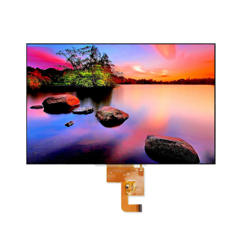
Ein TFT-LCD ist ein Flüssigkristallbildschirm mit aktiver Matrix, bei dem jedes Pixel durch ein eigenes Dünnschichttransistor-Schaltelement gesteuert wird. Das Panel besteht aus mehreren Schichten: einem Glassubstrat mit TFT-Arrays, einer Flüssigkristallschicht, einer RGB-Farbfilterschicht und Polarisatoren. TFT-LCDs sind transmissive Displays, die eine Hintergrundbeleuchtung benötigen; sie strahlen selbst kein Licht aus.
2.2 TFT-Panel-Typen und technische Daten
TFT ist eine weit gefasste Kategorie, die verschiedene Ausrichtungsmodi von Flüssigkristallen umfasst. Die drei Haupttypen sind Verdrehte Nematik (TN) , In-Plane Switching (IPS) , und Vertikale Ausrichtung (VA) . Jedes weist ganz eigene Leistungsmerkmale auf.
| Parameter | TN (Verdrehte Nematik) | IPS (In-Plane-Switching) | VA (Vertikale Ausrichtung) |
|---|---|---|---|
| Reaktionszeit | 1–5 ms | 5–12 ms | 5–8 ms (typisch) |
| Kontrastverhältnis (statisch) | ~800:1 | ~1000:1 | 3000:1 bis 6000:1 |
| Betrachtungswinkel (CR≥10) | 45°–55° pro Richtung | Bis zu 85° pro Richtung (insgesamt 178°) | Insgesamt 70°–120° |
| Farbraum (typisch) | 60–72% NTSC | 72–100% NTSC, bis zu 100% sRGB | 72% NTSC (typisch) |
| Lichtdurchlässigkeit | Höher | Unter | Mäßig |
Das Kontrastverhältnis eines TFT-LCD-Bildschirms ist definiert als das Verhältnis der Leuchtdichte zwischen dem hellsten Weiß und dem dunkelsten Schwarz, das der Bildschirm erzeugen kann. Typische TFT-LCD-Bildschirme bieten statische Kontrastverhältnisse im Bereich von 1000:1 bis 3000:1. Bei Panels im VA-Modus können die Werte 3000:1 übersteigen. Der Betrachtungswinkel wird in der Regel als der Winkel angegeben, bei dem das Kontrastverhältnis über 10:1 bleibt.
2.3 Luminanz und Helligkeit
Die Leuchtdichte von TFT-LCD-Displays wird in Candela pro Quadratmeter (cd/m²) gemessen, was gemeinhin als “Nits” bezeichnet wird. Standard-Displays für den Innenbereich liegen typischerweise im Bereich von 250 bis 500 cd/m². Varianten mit hoher Helligkeit für den Außenbereich oder für Anwendungen, die bei Sonnenlicht lesbar sein müssen, reichen von 700 bis 1.600 cd/m² oder mehr. Ein Display gilt im Allgemeinen als bei Sonnenlicht lesbar, wenn es eine Helligkeit von 700 cd/m² oder mehr aufweist, vorausgesetzt, das Kontrastverhältnis liegt bei Umgebungslicht über 5:1.
Durch das Hinzufügen einer Touchscreen-Schicht verringert sich die effektive Leuchtdichte. Ein typisches TFT-LCD mit einem Air-Gap-Touchscreen reflektiert etwa 14% des Umgebungslichts. Bei direkter Sonneneinstrahlung (Umgebungsbeleuchtung ~6000 cd/m²) kann diese reflektierte Komponente etwa 840 cd/m² erreichen, was den wahrgenommenen Kontrast erheblich verschlechtert.
2.4 Reaktionszeit
Die Reaktionszeit bei TFT-LCDs bezeichnet die Zeit, die Flüssigkristallmoleküle benötigen, um sich von einem Zustand in einen anderen auszurichten; sie wird in der Regel als Übergang von Schwarz nach Weiß (Tr) und von Weiß nach Schwarz (Td) oder als Grau-zu-Grau-Zeit (GtG) gemessen. Moderne TFT-LCDs erreichen Reaktionszeiten von 1–5 ms bei TN-Panels, 5–12 ms bei IPS-Panels und 5–8 ms bei VA-Panels. Im Vergleich dazu erreichen OLED-Displays Reaktionszeiten in der Größenordnung von 100 μs.
2.5 Farbraum
Der Farbraum definiert den Bereich der Farben, die ein Display wiedergeben kann. Der Farbraum von TFT-LCD-Displays wird in erster Linie durch die Eigenschaften der Hintergrundbeleuchtung und des Farbfilters bestimmt. TFT-Panels der Einstiegsklasse decken etwa 40–60% des NTSC-Farbraums ab. Standard-TFT-Displays decken 72% des NTSC-Farbraums ab, was in etwa 100% des sRGB-Farbraums entspricht. Hochwertige IPS-Panels mit Quantum-Dot-Technologie können eine DCI-P3-Abdeckung von über 95% erreichen.
2.6 Auflösung und Pixeldichte
Die Auflösungen von TFT-LCDs reichen von einfachem QVGA (320×240) bei kleinen Industriedisplays bis hin zu 4K-UHD (3840×2160) und darüber hinaus bei Verbraucheranwendungen. Typische Auflösungen für Industrie-Displays sind 640×480, 800×600 und 1024×768. Verbraucherdisplays verfügen üblicherweise über eine Auflösung von 1920×1080 (Full HD) oder 1920×1200 (WUXGA). Der Pixelabstand – also der Abstand zwischen benachbarten Pixeln derselben Farbe – liegt je nach Panelgröße und Auflösung typischerweise zwischen 0,1 mm und 0,3 mm.
3. Touchscreen Technologie
Ein Touchscreen ist ein Eingabegerät, das das Vorhandensein und die Position einer Berührung innerhalb des Anzeigebereichs erkennt. Im Gegensatz zu TFT-LCDs sind Touchscreens transparent, strahlen kein Licht aus und können nicht eigenständig als Anzeige dienen.
3.1 Resistive Touchscreens
Resistive Touchscreens arbeiten mit druckbasierter Erfassung. Der Aufbau besteht aus zwei leitfähigen Schichten, die durch isolierende Abstandshalter voneinander getrennt sind. Bei Druckausübung kommen die Schichten miteinander in Kontakt, wodurch ein Spannungsteiler entsteht, anhand dessen die Steuerung die Berührungsposition ermitteln kann.
Technische Daten:
| Parameter | 4-Draht-Widerstandsmessung | 5-Draht-Resistiv |
|---|---|---|
| Auflösung (Controller) | Bis zu 4096 × 4096 | Bis zu 4096 × 4096 |
| Reaktionszeit | ~10 ms | ~10 ms |
| Aktivierungskraft | ~1,40 N | ~1,40 N |
| Betriebsdauer | 1 Million Operationen | 10 Millionen Operationen |
| Berührungspunkte | Nur einmaliges Antippen | Nur einmaliges Antippen |
| Lichtdurchlässigkeit | ~80% (typisch) | ~80% (typisch) |
| Bedienung mit Handschuhen | Unterstützt | Unterstützt |
Resistive Touchscreens können nicht mehrere gleichzeitige Berührungen erfassen. Sie sind hinsichtlich der Eingabeauflösung weniger präzise als kapazitive Alternativen, lassen sich jedoch mit jedem beliebigen Gegenstand bedienen – sei es mit dem Finger, einem Stift oder einer behandschuhten Hand. Die 5-Draht-Konfiguration bietet im Vergleich zur 4-Draht-Variante eine überlegene Haltbarkeit.

3.2 Kapazitive Touchscreens
Kapazitive Touchscreens erfassen Kapazitätsänderungen, die durch die Annäherung oder den Kontakt eines leitfähigen Objekts – in der Regel eines menschlichen Fingers – verursacht werden. Der Bildschirm ist mit einem transparenten, leitfähigen Material beschichtet, meist Indium-Zinn-Oxid (ITO), und über die gesamte Oberfläche wird ein elektrostatisches Feld aufrechterhalten.
Oberflächenkapazitiv vs. projiziert-kapazitiv:
Kapazitiv (Oberflächenkapazitiv) Touchscreens verwenden Elektroden an den vier Ecken einer gleichmäßig beschichteten leitfähigen Schicht. Die Berührungsposition wird durch Messung des von jeder Ecke abgezogenen Stroms ermittelt. Diese Technologie unterstützt ausschließlich Ein-Finger-Bedienung.
Projektiv-kapazitiv (PCAP) Touchscreens verfügen über ein Raster aus strukturierten ITO-Elektroden, die in Zeilen (Ansteuerungsleitungen) und Spalten (Abtastleitungen) angeordnet sind. Dies ermöglicht die Erkennung von Mehrfingerberührungen und ist die vorherrschende Technologie in der modernen Unterhaltungselektronik.
Technische Daten (projektiv-kapazitiv):
| Parameter | Typischer Bereich |
|---|---|
| Mehrere Berührungspunkte | 5 bis 50+ Berührungen |
| Meldungsquote | 100–250 Hz |
| Positionsgenauigkeit | 99% (typisch) |
| Räumlicher Jitter | Bereits ab 0,11 mm |
| Signal-Rausch-Verhältnis | 54 dB (typisch) |
| Reaktionszeit | <3 ms |
| Lichtdurchlässigkeit | 88–92% |
| Lebenszyklus von Touch | Über 50 Millionen Vorgänge |
| Dicke des Deckglases | 0,7 mm (Standard) |
Die Melderate – also die Häufigkeit, mit der der Touch-Controller Positionsdaten an das Host-System übermittelt – ist ein entscheidender Leistungskennwert. Höhere Melderaten verringern die Latenz und verbessern die Flüssigkeit der Gestenerkennung. Moderne kapazitive Touch-Controller erreichen Melderaten von 100–250 Hz, wobei einige Implementierungen 120 Hz oder mehr erreichen.
Kapazitive Touchscreens sind aufgrund ihrer Deckglaskonstruktion langlebiger als resistive Modelle. Allerdings sind sie anfällig für Störungen durch Wasser, Feuchtigkeit und Kondenswasser, was zu Fehlbedienungen führen kann. Außerdem reagieren sie nicht auf nichtleitende Berührungen, wie sie beispielsweise bei normalen Handschuhen auftreten, obwohl es spezielle Steuerungen für den Handschuhmodus gibt.
3.3 Technische Daten des Touch-Controller-ICs
Der Touch-Controller ist der integrierte Schaltkreis, der die Rohdaten der Sensoren verarbeitet und die Berührungskoordinaten an den Host-Prozessor übermittelt.
Typische Spezifikationen eines Controllers (z. B. MAX11871):
- Bildwiederholrate: Bis zu 120 Hz
- Multi-Touch-Unterstützung: Echte Mehrpunkt-Erkennung
- Schnittstelle: I2C, SPI oder UART
- Betriebsspannung: typischerweise 2,8 V bis 3,3 V
Technische Daten des Widerstandsreglers (z. B. AR1010):
- Koordinaten-Meldungsrate: 140 Meldungen pro Sekunde (typisch)
- Auflösung: 10-Bit-ADC
- Schnittstelle: I2C, SPI, UART
4. Integration: TFT und Touchscreen in einem Gerät
Bei einem typischen Touch-Gerät sind das TFT-LCD-Panel und der Touchsensor vertikal übereinander angeordnet. Das TFT-LCD bildet den “inneren Bildschirm”, der für die Bildanzeige zuständig ist; der Touchsensor bildet den “äußeren Bildschirm”, der für die Berührungserkennung zuständig ist.
4.1 Stapelstruktur und optische Aspekte
Der optische Aufbau besteht in der Regel von unten nach oben aus folgenden Komponenten:
- Backlight-Einheit
- TFT-LCD-Panel (Display)
- Klebeschicht (Luftspalt oder optisch klarer Klebstoff)
- Berührungssensorschicht (ITO-Muster auf Glas oder Folie)
- Deckglas (mit Antireflexbeschichtung, optional)
Die Schnittstelle zwischen dem TFT-LCD und dem Berührungssensor ist entscheidend für die optische Leistung. Luftspaltverklebung Es bleibt eine dünne Luftschicht zwischen den beiden Komponenten zurück. Jede Grenzfläche zwischen Luft und Glas verursacht Fresnel-Reflexionsverluste von etwa 4–5%, was zu einem Gesamthelligkeitsverlust von 8–10% führt.
Optische Bindung ersetzt den Luftspalt durch einen optisch klaren Klebstoff (OCA) oder ein optisch klares Harz (OCR). Dadurch werden interne reflektierende Grenzflächen beseitigt, wodurch die Lichtdurchlässigkeit auf 90–95% erhöht wird. Das optische Verkleben verbessert zudem die Schlagfestigkeit, verhindert Kondensation und Beschlagen und erhöht den wahrgenommenen Kontrast. Die Klebstoffschicht erhöht die Gesamtdicke des Aufbaus lediglich um 25–50 Mikrometer.
4.2 Integrationsarchitekturen
Es gibt drei Hauptarchitekturen für die Integration von Touch-Funktionalität in TFT-LCD-Displays:
OGS (One Glass Solution): Der Berührungssensor wird direkt auf der Innenseite des Deckglases hergestellt. Das Deckglas dient gleichzeitig als Schutzschicht und als Substrat für den Berührungssensor. Dadurch lassen sich die Anzahl der Glasschichten und die Gesamtdicke reduzieren.
On-Cell: Die Elektroden des Berührungssensors sind auf der Außenfläche des Farbfiltersubstrats des TFT-LCDs aufgebracht – zwischen dem Displaypanel und dem Polarisator. Die Berührungsfunktion ist ohne zusätzliches Glassubstrat in die Struktur des Displaypanels integriert.
In-Cell: Der Berührungssensor ist in die Flüssigkristallschicht selbst eingebettet, wodurch die Berührungselektroden mit dem TFT-Array integriert werden. Dies ist der am stärksten integrierte Ansatz, der den dünnsten Schichtaufbau und die geringsten optischen Reflexionen ermöglicht. Allerdings bringt die In-Cell-Implementierung größere Herausforderungen hinsichtlich der elektromagnetischen Verträglichkeit mit sich.
| Architektur | Dicke | Optische Leistung | Komplexität in der Fertigung |
|---|---|---|---|
| OGS | Reduziert | Gut | Mäßig |
| On-Cell | Noch weiter reduziert | Besser | Höher |
| In-Cell | Dünnstes | Am besten | Höchste |
5. Wesentliche Unterschiede: Zusammenfassung
| Aspekt | TFT-LCD | Touchscreen |
|---|---|---|
| Funktion | Bildanzeige | Erkennung von Berührungs-Eingaben |
| Technikunterricht | Anzeige | Eingangssensor |
| Licht-Emission | Ja (hintergrundbeleuchtet, transmissiv) | Nein (transparent) |
| Autonomer Betrieb | Ja (zeigt nur Bilder an) | Nein (erfordert Anzeige darunter) |
| Wichtige Parameter | Auflösung, Helligkeit, Kontrast, Reaktionszeit, Farbraum, Betrachtungswinkel | Übertragungsrate, Genauigkeit, Multi-Touch-Unterstützung, Betätigungskraft, Lichtdurchlässigkeit |
| Primärmaterialien | Glassubstrate, Flüssigkristalle, Farbfilter, Polarisatoren, Hintergrundbeleuchtung | ITO-beschichtetes Glas/Folie, Deckglas, Steuer-IC |
6. Anwendungsspezifische Überlegungen
Unterhaltungselektronik (Smartphones, Tablets):
- Display: IPS-TFT-LCD oder OLED
- Touch: Projektiv-kapazitiv, 5–10 Multitouch-Punkte
- Integration: In-Cell oder On-Cell für geringere Dicke
- Typische Helligkeit: 400–800 cd/m²
Industrielle Steuerung und HMI:
- Display: TN- oder IPS-TFT-LCD, oft mit großem Temperaturbereich (-20 °C bis +70 °C)
- Touch: Resistiv (für die Bedienung mit Handschuhen) oder PCAP
- Integration: Luftspalt oder optisch verbunden
- Typische Helligkeit: 250–1000 cd/m²
- Verlängerte Betriebsdauer: über 50.000 Stunden
Anwendungen im Außenbereich/an Kiosken:
- Display: TFT-LCD mit hoher Helligkeit (700–1600 cd/m²)
- Touch: Resistiv (langlebig) oder PCAP mit Handschuhunterstützung
- Integration: Optisches Bonding ist für die Lesbarkeit unerlässlich
- Antireflex- und Blendschutzbeschichtungen
Medizinische Geräte:
- Display: Hochpräzises IPS-TFT-LCD mit Farbkalibrierung
- Touch: PCAP für Reaktionsschnelligkeit
- Optisches Bonding für Klarheit und zum Schutz vor Verunreinigungen
Kontaktieren Sie uns für technische Lösungen