








Introduction – Understanding Display Technologies at the Component Level
Display technology choices have profound implications for system performance, reliability, and total cost of ownership—particularly in industrial automation, medical imaging, enterprise IT infrastructure, and embedded systems. Yet a fundamental confusion persists: what actually differentiates LCD, TFT, and CRT?
The critical distinction that every engineer and procurement professional must understand is this: LCD (Liquid Crystal Display) is a broad category, while TFT (Thin Film Transistor) is a specific, high-performance implementation within that category. All TFT displays are LCDs, but not all LCDs are TFTs. The non-TFT variants—passive-matrix LCDs such as STN (Super Twisted Nematic)—suffer from slow response times, crosstalk, and limited image quality, making them unsuitable for most engineering and industrial applications.
CRT (Cathode Ray Tube), meanwhile, represents the analog legacy technology that defined the 20th century. Though long discontinued from mainstream production, CRT displays persist in legacy systems—aging CNC machinery, military radar terminals, and certain medical equipment—requiring engineers to understand both their replacement strategies and their lingering technical advantages.
This article provides a comprehensive technical specification comparison across the full spectrum of display parameters: brightness, contrast ratio, color depth, response time, viewing angle, resolution behavior, power consumption, electromagnetic compatibility, and environmental tolerance. Every specification is grounded in engineering data and sourced from authoritative technical references.
Section 1 – Display Technology Fundamentals: How Each Works
CRT (Cathode Ray Tube): The Analog Electron-Beam System
A CRT is essentially a sealed vacuum tube containing an electron gun at its neck and a phosphor-coated screen at its face. The operational sequence is as follows:
- A cathode is heated to liberate electrons via thermionic emission
- Electrons are accelerated toward the screen by a high-voltage anode (typically >20 kV)
- Deflection coils direct the electron beam horizontally and vertically in a raster scan pattern
- The beam strikes phosphor dots on the inner screen surface, causing them to emit light
Color CRTs employ three separate electron guns—one each for red, green, and blue phosphors. A shadow mask or aperture grille ensures each gun strikes only its corresponding phosphor color. The image is drawn line by line, with the electron beam scanning the entire screen 50–160 times per second (vertical refresh rate).
Key engineering parameters:
- Video Bandwidth: 110–205 MHz, determining the maximum resolution and refresh rate combination the CRT can support
- Dot Pitch / Aperture Grille Pitch: 0.21–0.27 mm, governing theoretical resolution limits
- Scanning Method: Progressive (all lines drawn sequentially) or interlaced (odd/even fields alternated)
LCD (Liquid Crystal Display) – The Generic Electro-Optical Category
LCD technology relies on the electro-optic properties of liquid crystal molecules. In a typical transmissive LCD:
- A backlight (historically CCFL, now predominantly LED) provides a uniform light source
- Light passes through a polarizer, becoming linearly polarized
- The polarized light travels through a liquid crystal layer
- Voltage applied across the liquid crystal causes molecules to twist, rotating the polarization plane
- A second polarizer (analyzer) blocks or passes light depending on the polarization state
- A color filter array (RGB stripes) assigns color to each sub-pixel
The LCD category divides into two fundamental classes:
| Class | Technology | Characteristics |
|---|---|---|
| Passive Matrix | STN (Super Twisted Nematic), DSTN | Row/column electrodes drive pixels; slow response (150–300 ms); crosstalk between adjacent pixels; poor image quality |
| Active Matrix | TFT-LCD | Each pixel has a dedicated thin-film transistor switch; fast response; high contrast; no crosstalk; the only class acceptable for engineering applications |
TFT (Thin Film Transistor) – The Active-Matrix Implementation
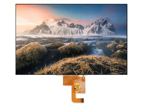
TFT-LCD is the dominant active-matrix technology. Each pixel contains a thin-film transistor—typically fabricated from a-Si (amorphous silicon) or LTPS (low-temperature poly-silicon)—that acts as an independent switch, controlling the voltage applied to that pixel’s liquid crystal cell. This eliminates crosstalk and enables precise grayscale control.
The TFT panel sub-families—critical for engineering selection:
| Panel Type | Viewing Angle | Contrast Ratio | Response Time | Color Accuracy | Best Application |
|---|---|---|---|---|---|
| TN (Twisted Nematic) | Narrow (~140°/120°) | ~600–1000:1 | Fastest (0.5–5 ms) | Poor color; color shift off-axis | Cost-sensitive, fast-response applications |
| IPS (In-Plane Switching) | Wide (178°/178°) | ~1000:1 | Good (5–14 ms) | Excellent; minimal color shift | Color-critical work, medical imaging, wide-viewing applications |
| VA (Vertical Alignment) | Moderate (~160–178°) | Highest (3000:1+) | Moderate (16–25 ms) | Good | High-contrast applications, surveillance, HMI |
| FFS (Fringe Field Switching) | Wide (178°/178°) | ~900–1500:1 | Good (30 ms) | Excellent; higher transmittance than IPS | High-end mobile and industrial displays |
Critical procurement warning: A specification that reads merely “LCD” is insufficient. Engineering contracts must specify “Active Matrix TFT-LCD” and identify the panel type (TN/IPS/VA/FFS) to avoid delivery of inferior passive-matrix displays.
Section 2 – Full Technical Specification Comparison (CRT vs. TFT-LCD)
The following table provides a comprehensive, side-by-side comparison of every major technical parameter:
| Parameter | CRT (Cathode Ray Tube) | TFT-LCD (Thin Film Transistor) | Engineering Interpretation |
|---|---|---|---|
| Brightness (Luminance) | 80–120 cd/m² (typical); high-brightness variants up to 250 cd/m² | 170–500 cd/m² (commercial); industrial high-brightness: 1000–1600 cd/m² | TFT offers 2–10× higher brightness; critical for outdoor/sunlight-readable applications |
| Contrast Ratio | 350:1 to 700:1 (typical) | 150:1 to 450:1 (early); modern: 1000:1 (IPS); VA: 2500:1+ | CRT’s true black (no backlight bleed) gives theoretical advantage; modern VA panels approach or exceed CRT contrast |
| Color Gamut | Theoretically unlimited (analog signal, no bit-depth quantization) | NTSC 60–72% (standard); professional: 100%+ Adobe RGB | CRT retains theoretical advantage in color reproduction; TFT has largely closed the gap in practice |
| Color Depth | Analog infinite gradation; no quantization error | 6-bit + FRC (262k colors); 8-bit (16.7M colors); 10-bit (1.07B colors) | 8-bit minimum for professional applications; 10-bit for medical/color-critical work |
| Response Time | <1 ms (electron beam instantaneous); effectively invisible | 20–50 ms (early); modern: 5–14 ms (TN: 0.5–5 ms) | CRT still superior for ultra-fast motion; modern TFT sufficient for >95% of applications |
| Viewing Angle | >150° (essentially unlimited) | TN: ~140°; IPS/FFS: 178°/178°; wide-view TFT: 89°/89°/89°/89° | IPS/FFS required for multi-viewer or off-axis applications |
| Native Resolution | None—supports multiple resolutions flexibly | Fixed—must run at physical resolution; scaling causes blur | System design must match GPU output to panel’s native resolution |
| Refresh Rate | 50–160 Hz variable; >85 Hz flicker-free | Fixed 60 Hz (typical); high-refresh: 120 Hz+ | CRT refresh governs flicker; TFT refresh governs frame update—different physical phenomena |
| Convergence Error | 0.20–0.30 mm possible (RGB guns misalignment) | None—each pixel independently controlled | TFT provides sharper text and finer detail |
| Geometric Distortion | Possible (pincushion/barrel) | Perfect—no geometric errors | TFT essential for CAD, precision mapping |
| Defective Pixels | None—no “stuck” pixels | Possible (dead/bright pixels) | Contracts must specify ISO 13406-2 pixel defect class |
| Power Consumption | 58–160 W (17–19″ typical) | 18–48 W (industrial TFT); 6–8 W (small industrial) | TFT 3–5× more energy-efficient; significant TCO advantage |
| Electromagnetic Emissions | Significant—high-voltage electron beam generates EMI | Minimal—low-voltage digital drive | TFT easier to certify for industrial EMC compliance |
| Physical Footprint | Depth >400 mm; weight 15–22 kg | Depth <50 mm; weight <5 kg | TFT enables VESA mounting, rack integration, space-constrained installations |
| MTBF (Backlight/Lifespan) | 30,000–50,000 hours (CRT tube aging) | LED backlight: 50,000–100,000 hours | TFT offers 2× longer service life with lower maintenance |
Section 3 – In-Depth Performance Analysis by Application Scenario
Scenario A: Static Image Display (Office, CAD, Medical PACS)
CRT performance: No geometric distortion concerns, but text sharpness is limited by convergence error (0.20–0.30 mm)—the three electron beams may not align perfectly, causing color fringing around fine text.
TFT performance: At native resolution, text is exceptionally sharp—each pixel is precisely defined with no analog alignment error. IPS panels with 8-bit or 10-bit color depth deliver excellent grayscale rendition for medical PACS applications.
Engineering verdict: TFT wins decisively. For medical applications, ensure the display complies with DICOM Part 14 grayscale display function and incorporates built-in backlight sensors for luminance stability.
Scenario B: Fast-Motion Video & Machine Vision
CRT performance: Response time is effectively instantaneous (<1 ms)—no motion blur, no ghosting. The electron beam refreshes each pixel virtually instantly.
TFT performance: Early TFTs suffered 20–50 ms response times, producing visible motion blur. Modern fast-response panels (TN: 0.5–5 ms) have dramatically improved. However, “response time” and “refresh rate” are distinct parameters—both affect motion quality.
Engineering verdict: CRT retains a theoretical advantage for ultra-high-speed motion. However, modern high-refresh TFTs (120 Hz+) with <5 ms GtG response are sufficient for >95% of industrial machine vision and surveillance applications.
Scenario C: Professional Color Grading & Print Proofing
CRT performance: Wide color gamut, accurate color reproduction, deep blacks, and no quantization loss made CRT the gold standard for color-critical work for decades.
TFT performance: Modern 10-bit IPS panels with 100%+ Adobe RGB coverage have largely closed the gap. However, black levels remain a limitation—LCD backlight bleed prevents the “true black” achievable on CRT.
Engineering verdict: High-end TFT (10-bit IPS with hardware calibration) is now the practical standard. CRT is obsolete for new installations, though some legacy workflows may still prefer it.
Scenario D: Industrial & Outdoor Harsh Environments
CRT performance: Temperature-insensitive and immune to liquid crystal slowdown at low temperatures. However, susceptible to vibration (filament breakage) and magnetic field interference.
TFT performance: Grade selection is critical. Commercial-grade TFT: 0–50°C operating range. Industrial wide-temperature TFT: –20°C to +70°C; automotive-grade extends to –30°C to +85°C. High-brightness variants (>1000 cd/m²) ensure sunlight readability.
Engineering verdict: Wide-temperature industrial TFT is the only viable solution for new industrial installations. CRT is no longer available as new product.
Scenario E: Legacy System Maintenance (CRT Replacement)
For systems with legacy CRT interfaces (e.g., vintage CNC machines, old medical endoscopy systems), direct CRT replacement is increasingly difficult—new CRTs have been discontinued.
Recommended engineering approach: Specify a TFT-LCD retrofit kit—an industrial TFT panel with an integrated signal conversion board that translates the legacy analog video signal (VGA, composite, or proprietary) to the TFT’s digital interface. This provides a longer-term, more cost-effective solution than sourcing second-hand CRT tubes with uncertain remaining life.
Section 4 – Technical FAQs for Engineers
Q1: Why do some displays labeled “LCD” have slow response and narrow viewing angles?
A: “LCD” is a broad category encompassing both passive-matrix (STN) and active-matrix (TFT) technologies. Passive-matrix displays use row/column electrodes without per-pixel transistors, resulting in slow response, crosstalk, and poor viewing angles. Engineering specifications must explicitly state “Active Matrix TFT-LCD” and identify the panel type (TN/IPS/VA/FFS).
Q2: Why does a TFT display look blurry at non-native resolutions?
A: TFT panels have a fixed physical pixel array. When fed a non-native resolution, the display’s scaler (scaling engine) must interpolate the image to fit the physical pixels—a process that introduces blur and artifacts. System architects must ensure the graphics output matches the panel’s native resolution exactly.
Q3: What is the TFT equivalent of CRT “bandwidth”?
A: CRT bandwidth (measured in MHz) determines the maximum resolution × refresh rate combination the analog electronics can process. TFT has no direct equivalent—its capabilities are governed by the timing controller (TCON) and signal interface data rate (LVDS, eDP, or HDMI bandwidth). These determine the maximum pixel clock and thus the maximum resolution and refresh rate.
Q4: Are “response time” and “refresh rate” the same thing?
A: No—they measure different physical phenomena:
- Response time (ms): The time required for a liquid crystal pixel to transition from one grayscale level to another. Determines motion blur/ghosting.
- Refresh rate (Hz): The number of times per second the display updates the entire frame. Determines motion smoothness and tearing.
Both parameters independently affect motion quality and must be considered together.
Q5: What MTBF can I expect from industrial TFT displays?
A: Industrial-grade TFT modules typically offer 50,000–100,000 hours MTBF for the LED backlight. The LCD panel itself can exceed this. Compare this to CRT’s typical 30,000–50,000 hour lifespan—TFT offers 2× longer service life with lower maintenance requirements. Procurement contracts should request MTBF test reports from the supplier.
Q6: What pixel defect standard should I specify in procurement contracts?
A: Specify ISO 13406-2 pixel defect classification. For industrial and medical applications, Class I (zero defective pixels) or Class II (very few permitted) is typical. Define acceptance criteria clearly in the technical specification to avoid disputes during incoming inspection.
Section 5 – Technical Selection Decision Matrix
| Selection Criterion | Priority Metric | CRT | TFT-LCD | Recommendation |
|---|---|---|---|---|
| Color Accuracy | Color gamut, bit depth, black level | ★★★★★ | ★★★★☆ (10-bit IPS) | CRT has theoretical advantage; TFT sufficient for >95% of applications |
| Motion Clarity | Response time, motion blur | ★★★★★ | ★★★★☆ (modern fast panels) | CRT still superior for ultra-high-speed; TFT adequate for most |
| Text Sharpness | Convergence error, native resolution | ★★★☆☆ | ★★★★★ | TFT wins decisively |
| Physical Integration | Depth, weight, mounting options | ★☆☆☆☆ | ★★★★★ | TFT wins decisively |
| Energy Efficiency | Power consumption, heat dissipation | ★☆☆☆☆ | ★★★★★ | TFT wins decisively—3–5× lower power |
| Environmental Tolerance | Wide temperature, vibration, shock | ★★★☆☆ | ★★★★☆ (industrial grade) | Wide-temp TFT is the modern standard |
| Supply Chain Stability | New product availability, spare parts | ★☆☆☆☆ (discontinued) | ★★★★★ | TFT is the only viable choice for new designs |
Conclusion & Technical Summary
The CRT Legacy
CRT technology retains genuine technical advantages in three areas: instantaneous response time (<1 ms), true black levels (no backlight bleed), and theoretically unlimited color gradation. However, CRTs are no longer in production, suffer from high power consumption (58–160 W), massive physical footprint, electromagnetic emissions, and limited lifespan.
The TFT Reality
Modern TFT-LCD technology has matured into a robust, high-performance engineering solution. In brightness (170–1600 cd/m²), text sharpness, power efficiency (18–48 W), physical integration, and service life (50,000–100,000 hours), TFT decisively exceeds CRT. In color accuracy and motion response, TFT has substantially closed the gap—modern 10-bit IPS panels and sub-5 ms response panels meet the requirements of all but the most extreme professional applications.