Introduction
Choosing the wrong LCD interface can delay your project by weeks, force a PCB redesign, or even kill your product’s performance. Whether you are an embedded engineer, a hardware manager, or a product owner, this guide will help you understand the six most common TFT-LCD interfaces, compare their trade‑offs, and quickly select the right one for your application.
By the end of this 5,000‑word guide, you will be able to:
- Identify which interface fits your resolution, frame rate, and cost targets.
- Avoid common pitfalls like pin‑count overflow or EMI failures.
- Download a free LCD Interface Quick Reference Sheet (PDF).
Let’s start with the most important question.
Why Does the Interface Choice Matter So Much?
The interface defines how your microcontroller or processor talks to the display. It directly affects:
- Pin count – how many I/Os or PCB traces you need.
- Maximum resolution and refresh rate – what the link can sustain.
- Electromagnetic interference (EMI) – critical for medical, automotive, or industrial devices.
- Cable length – whether you can place the display away from the main board.
- Host controller cost – some interfaces require dedicated hardware (LVDS transmitter, MIPI DSI host, external frame buffer).
Quick Reference – Six TFT‑LCD Interfaces at a Glance
| Interface | Typical Application | Pins (approx.) | Max Resolution | Refresh Rate (typical) | Cable Distance (board‑level) | EMI Immunity | Host Requirement |
|---|---|---|---|---|---|---|---|
| MCU (8080/6800) | Small, low‑cost embedded | 8–16+ | 480×320 | 15–30 fps | <10 cm | Moderate | Any MCU (GPIO) |
| RGB parallel | Medium size, external frame buffer | 24+ (RGB888) | 1024×768 | 60+ fps | <10 cm | Moderate | LCD controller or external RAM |
| LVDS | Large, industrial / automotive | 4–10 | 1920×1080 | 60–120 fps | Up to several meters | Excellent | LVDS transmitter (or integrated) |
| MIPI DSI | Smartphones, wearables, tablets | 2–4 lanes | 4K (per lane up to 1.5 Gbps) | 60–120 fps | <20 cm | Excellent | MIPI DSI host |
| eDP | Laptops, high‑end monitors | 2–4 lanes | 8K+ | 60–240 Hz | Up to 30 cm | Excellent | eDP source |
| SPI / I2C | Very low resolution, low refresh | 3–6 | 128×64 (colour) | <10 fps | <20 cm | Moderate | Any MCU |
Each interface name in the table links to its detailed section below.
Detailed Explanation of Each Interface
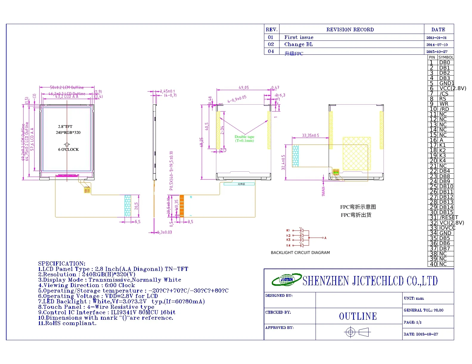
1. MCU Interface (8080 / 6800 Parallel Bus)
How it works
The host writes directly to the LCD’s internal GRAM using a parallel bus, exactly like accessing an external SRAM. The display controller (e.g., ILI9341, ST7789) holds the frame buffer.
Advantages
- Works with any MCU (no dedicated LCD peripheral needed).
- Timing can be bit‑banged with GPIOs.
- Stable refresh rate (no dependency on host real‑time rendering).
Disadvantages
- High pin count (8 or 16 data lines + RD/WR/RS/CS).
- Limited resolution – GRAM bandwidth becomes the bottleneck.
- For resolutions above 480×320, the frame rate often drops below 15 fps.
Typical controller ICs
ILI9341 (2.4″), ST7789 (1.3″–2.4″).
Debug tip
A very common fault: incorrect RS (Command/Data) level, causing the LCD to interpret commands as pixel data or vice versa. Another: slow bus timing produces a “snowy” display.
2. RGB Parallel Interface (Pixel Synchronous)
How it works
The host outputs pixel clock (DOTCLK), horizontal sync (HSYNC), vertical sync (VSYNC), data enable (DE), and 24‑bit RGB data. The LCD module does not contain a GRAM; an external frame buffer (or the host’s built‑in LCD controller) must continuously stream frames.
Advantages
- Supports high resolution and high refresh rate (60 fps+).
- Lower module cost (no on‑board GRAM).
Disadvantages
- Heavy host load – must render and stream every frame in real time.
- High pin count: at least 24 data lines + 3 sync + clock.
- Sensitive to PCB trace length and noise.
Typical applications
4.3″ to 10.1″ industrial HMIs, medical monitors.
3. LVDS (Low‑Voltage Differential Signaling)
How it works
LVDS converts the parallel RGB bus into serialised low‑voltage differential pairs. Each differential pair transmits 7 bits of data. Common configurations: 4 data pairs + 1 clock pair (for 24‑bit colour).
Advantages
- Excellent noise immunity – differential signalling rejects common‑mode noise.
- Long cable length: up to several meters (ideal for displays mounted away from the main board).
- Low pin count (only 4–10 pins).
- Supports high resolution (1080p, 4K with multiple links).
Disadvantages
- Requires an LVDS transmitter on the host side (or a host with integrated LVDS).
- PCB layout must control differential impedance (typically 100Ω ±10%) and maintain length matching.
Typical applications
Automotive infotainment, industrial HMIs, large medical displays.
4. MIPI DSI (Mobile Industry Processor Interface – Display Serial Interface)
How it works
MIPI DSI is a high‑speed differential serial interface. It operates in two modes:
- Command mode – similar to MCU interface; display contains a full GRAM. Ideal for low‑power static content.
- Video mode – similar to RGB interface; no GRAM, host streams real‑time video.
Each lane can run up to 1.5 Gbps (or higher in newer DSI‑2).
Advantages
- Very low pin count: 2‑4 data lanes + clock.
- Low power consumption (supports partial refresh and sleep modes).
- Bidirectional communication (you can read back register values or status).
Disadvantages
- Host must have a MIPI DSI master – not available on low‑end MCUs.
- Protocol debug is more complex than parallel interfaces.
- Strict impedance control (100Ω differential) and trace matching.
Typical applications
Smartphones, smartwatches, tablets, AR/VR headsets.
5. eDP (Embedded DisplayPort)
How it works
Based on the DisplayPort standard, eDP uses micro‑packet architecture. It can carry video, audio, and auxiliary data (backlight control, touch panel, etc.) over the same link. Link rates reach 8.1 Gbps per lane (HBR3).
Advantages
- Ultra‑high resolution (8K and beyond).
- Variable refresh rate (VRR) for smooth video playback.
- Fewer EMI issues compared to LVDS at very high resolutions.
Disadvantages
- High host cost – eDP source is found mainly on laptop/tablet processors.
- Overkill for small or low‑resolution displays.
Typical applications
Notebooks, all‑in‑one PCs, high‑end tablets.
6. SPI / I²C (Serial Interfaces)
How it works
Data is shifted serially into the LCD’s internal GRAM. SPI is used for colour graphic displays; I²C is common for character or segment displays.
Advantages
- Extremely low pin count: SPI needs 4 pins (CS, DCX, SCL, SDA); I²C needs 2 (SCL, SDA).
- Works with any MCU (even tiny 8‑bit ones).
Disadvantages
- Very low refresh rate – not suitable for video or dynamic graphics.
- Limited resolution: SPI colour displays rarely exceed 240×240.
Typical controllers
SSD1306 (OLED), ST7735 (1.8″ colour TFT).
Debug tip
A common mistake: grounding the CS pin permanently, which prevents the host from switching between command and data bytes. Always toggle CS or use DCX.
Decision Tree: How to Choose the Right Interface for Your Project
Follow this step‑by‑step decision flow (image described in text):
- Do you need a high refresh rate (>30 fps) for video or smooth animation?
- NO → Check pin‑count limitation.
- If extremely limited (≤6 pins) → SPI / I²C
- If 8‑16 pins available → MCU interface (for resolutions ≤480×320)
- YES → Go to next step.
- Is the resolution > 1024×768?
- NO → Consider RGB parallel (if host can handle real‑time streaming).
- Or MCU if you can accept lower frame rate.
- YES → Go to next step.
- Is the cable length > 30 cm (display separated from main board)?
- YES → LVDS (up to several meters) or eDP (shorter, but still good).
- NO →
- For mobile / battery‑powered → MIPI DSI (low pin count, low power).
- For laptop / desktop → eDP (high resolution, VRR).
- For industrial / automotive with moderate length → LVDS.
Common Interface Mistakes and How to Avoid Them
❌ Mistake 1: Using MCU interface for 480×272 or higher resolution
Symptoms: Frame rate drops to 10‑15 fps, UI feels sluggish.
Solution: Move to RGB parallel (if host can stream) or LVDS. Even a simple FPGA‑based RGB driver can dramatically increase throughput.
❌ Mistake 2: LVDS layout ignoring differential impedance and length matching
Symptoms: Screen flickers, random pixels, unstable image.
Solution: Control differential impedance to 100Ω (for LVDS) and keep intra‑pair skew < 5 ps.
Download our free “LVDS PCB Layout Checklist”.
❌ Mistake 3: Assuming MIPI DSI Command Mode eliminates the need for a frame buffer
Clarification: Command mode displays do have an internal GRAM – that’s why they can stay static without host refresh. Video mode displays have no GRAM and require constant streaming. Choose based on your power and update rate needs.
❌ Mistake 4: Tying SPI CS (chip select) permanently low
Symptoms: The LCD does not distinguish between commands and data.
Fix: Use a GPIO to toggle CS (or at least use DCX properly). For SPI, DCX must be toggled while CS is active.
Conclusion & Next Steps
The right TFT‑LCD interface balances resolution, frame rate, pin count, EMI, and host capabilities. Use the decision tree above to shortlist candidates, then validate with your specific display module’s datasheet.
What to do now?
✅ Download the free LCD Interface Quick Reference Sheet – a one‑page PDF summarising max resolutions, typical ICs, and layout tips for all six interfaces.
✅ Still unsure? Submit your project parameters (resolution, refresh rate, cable length, host MCU/MPU) to JICLCD – our engineers will recommend the optimal interface within 24 hours.
✅ Browse our standard product library – filter by interface type to find a display that matches your choice.
Custom LCD service